


Measure Rise & Fall Time using HSDIO / Digital Pattern Generator
Measure Rise and Fall time without an oscilloscope, using HSDIO (PXI 6556) or Digital Pattern Generator (PXI 6570 or PXI 6571)
Whether your interest is in simply measuring rise and fall time or in controlling rise and fall time, you need a way to measure these parameters. This is because rise and fall time is best controlled by indirect means (such as current limit control on a PPMU line) that also require an independent way to measure and calibrate the rise and fall times obtained.
The rise time and fall time of a signal are usually measured using an oscilloscope. In applications involving digital system validation (especially protocol validation), most of the digital timing measurements do not require a scope; except for rise and fall time measurements.
“What if you could eliminate the use of the oscilloscope for rise and fall time measurements and reduce inventory cost?”
In this article, we show you a proven method of measuring rise and fall time of signals using NI’s High-Speed Digital IO instruments or Digital Pattern Generator devices. Thus, an analog measurement is achieved using a digital generation and acquisition device. How did we achieve that?
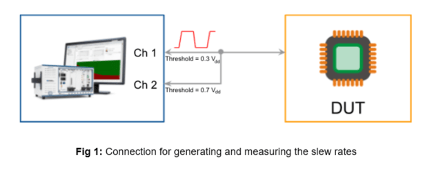
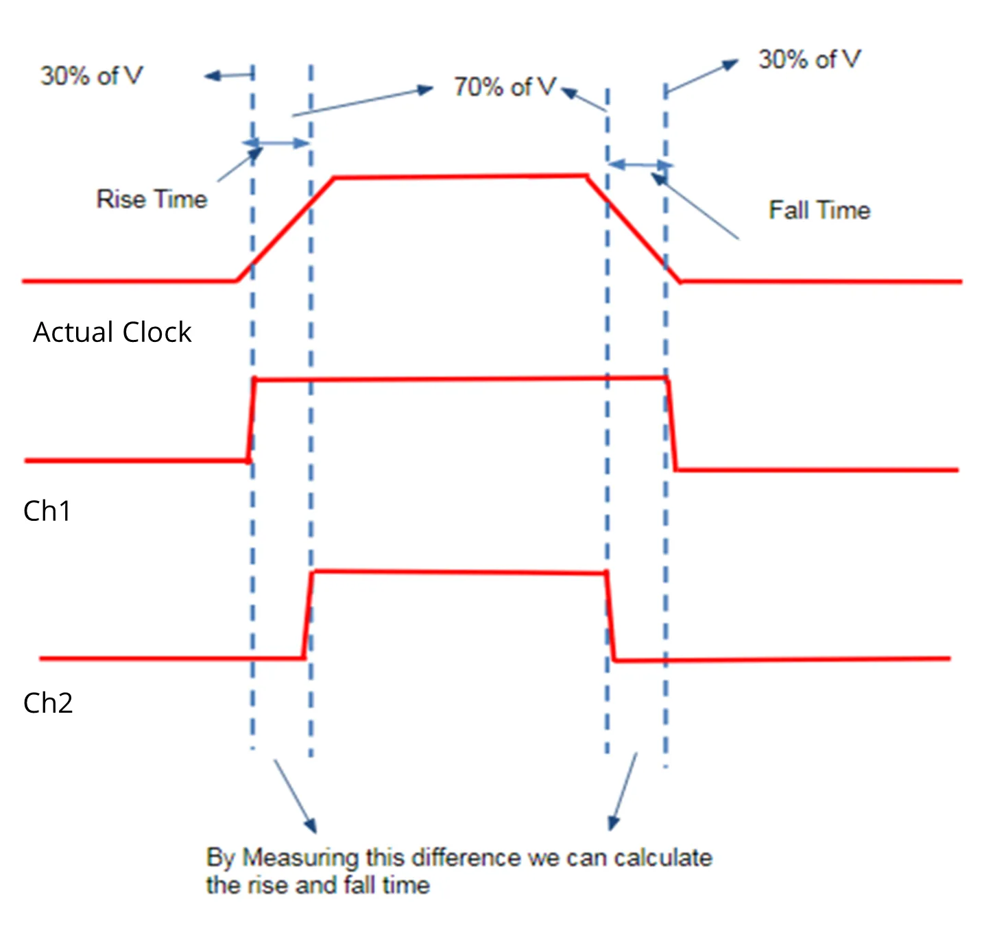
Fig 2: Typical signal and the captured digital traces
When using NI HSDIO, the pin where we want to measure rise and fall time is connected to two separate digital inputs (channels) with cables of the same length. The PXIe-6556, PXIe-6570, and PXIe-6571 have software APIs that can control the voltage input threshold of each channel individually. With this feature, we should be able to capture the rising edge signal on two channels with two different thresholds (Channel 1 set to 30% and Channel 2 set to 70% of VDD). The time difference between the Low-to-High edge transition (0 to 1 in the digital domain) on the two channels should give the rising time of the signal. Similarly, the difference between the High-to-Low edges on the two channels (1 to 0 in the digital domain) should represent the fall time. Propagation delay may be expected between the two capture paths for the two channels, and this has to be compensated by a calibration process. To calibrate the setup, pass a known signal to the two channels; but this time, capture the pulse with the same input voltage threshold value on both channels. The delay between the rising edges in the digital domain is the ‘delay measurement error ’, which should be factored in during runtime.
Isn’t that simple? With this approach, one can save the inventory cost of an oscilloscope for digital protocol validation applications.
“A rise and fall time measurement accuracy of +/-10ns for the NI DigiPat or HSDIO devices is possible with most measurements being within +/-5ns of an oscilloscope measurement.”
Written by
Arvind Balachandran
Oct 14, 2018