

How Error Injection Improves Peripheral Robustness: Featuring MIPI SoundWire and SWI3S
Every electronic product works perfectly in the lab. The real question is what happens after it ships. Connectors wear out over time, power supplies become unstable, nearby electronics create interference, and the quality of signals on the wires drops. When that happens, a well-designed device must keep functioning or at the very least, fail predictably and recover cleanly.
Specifications describe how a device should behave when things go wrong. But most validation strategies only prove that the device works under clean, well-formed traffic. They never answer the harder question: Is the device robust when conditions degrade?
The only reliable way to find out is to deliberately make things go wrong and watch how the device responds. That practice is called error injection, and this blog walks through how it works, why it matters, and what it looks like in practice using MIPI SoundWire. This audio interface builds a detailed error model directly into its protocol. The same principles apply to SWI3S (SoundWire I3S), the newer interface in the same MIPI audio family, so the examples below also apply to it.
What is Error Injection?
Error injection is the deliberate creation of faults (corrupted messages, broken timing, or electrical disturbances) under controlled conditions to verify that a device responds the way its specification requires.
Think of it like a fire drill for electronics. A fire drill doesn’t prove the building is fireproof; it proves that everyone knows what to do when the alarm sounds. In the same way, error injection doesn’t prevent faults from ever occurring; it proves that when a fault does occur, the device detects it, contains it, and recovers from it without leaving the system in a confused or half-configured state.
Why It Matters on Any Digital Interface
Modern interface specifications define far more than how data flows. They also spell out explicit error-detection and recovery behaviour: how a device notices that it has lost synchronization, how status flags are raised, how interrupts escalate problems to the host, and how a transaction that is interrupted mid-way is cancelled cleanly, so shared configuration is never left half-updated.
Here is the uncomfortable truth: a device can pass an extensive functional test suite while still mishandling the very error conditions its specification was designed to make recoverable. Those recovery paths simply never get exercised by normal, well-behaved traffic.
A structured error-injection strategy closes that gap. Validation engineers deliberately create malformed messages, timing violations, and electrical conflicts, then observe whether the device moves through the states that the specification defined for recovery and robustness.
SoundWire in Brief
MIPI SoundWire is the interface that carries audio inside many modern laptops, phones, and headsets. In its basic form, it is just two wires, a Clock line and a Data line, connecting one controller, called the Manager, to one or more audio devices, called Peripherals (microphones, speaker amplifiers, codecs).
The Manager drives the Clock continuously and defines the Frame structure, organizing the bitstream into repeating units called Frames. The Data line itself is shared: Peripherals drive their responses and audio payload in the BitSlots allocated to them. Each Frame reserves the first 48 BitSlots of its first column (Column 0, Rows 0–47) for the Control Word, which carries synchronization patterns, commands, responses, and a parity check. These control bits are interleaved with the audio bits row by row rather than sitting in one contiguous block, while the remaining bit slots carry the actual audio through Data Ports.
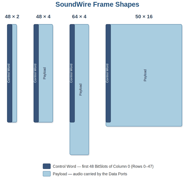
Figure 1 SoundWire Frame Shapes
SoundWire is an ideal example for this discussion because its specification builds an error model directly into the protocol: synchronization fields the Peripheral must continuously verify, parity protection on traffic, response bits that classify the outcome of every command, a defined device state machine, a graded reset hierarchy, and a clever line encoding that even lets a device detect when two devices accidentally drive the bus at the same time. Every one of these is a recovery path and every recovery path can be tested through error injection.
SWI3S (SoundWire I3S), the newer interface in the same MIPI audio family, keeps the same Manager-and-Peripheral structure and a similar overall approach to error handling, so the validation strategy below applies to it too. Some mechanisms differ. For example, SWI3S protects its command traffic with a CRC rather than a single parity bit, and it manages shared-bus access through scheduled handovers. The validation approach carries over essentially unchanged.
A Practical Roadmap for Error Injection
Whatever the interface, a reusable error-injection strategy follows the same four steps:
.png)
Figure 2 Error Injection Roadmap
1. Map spec requirements to error types. Go through the specification and identify which faults can be triggered directly on the bus, and which require physical-layer manipulation of the signals themselves.
2. Build a configurable injection layer. Extend the Manager, a bus monitor, or an external instrument so it can corrupt specific bits, force synchronization mismatches, create drive conflicts at precisely controlled instants, and sequence resets and low-power transitions in both legal and illegal orders.
3. Instrument the Peripheral for observability. This step is easy to underestimate, but without observability, an injected fault yields no useful information. Build the system such that State-machine indicators, interrupt status registers, response fields, and error counters are all accessible. By noting down these fields, we can conclude that the device behaves as defined in the specification.
4. Correlate protocol behaviour with system outcomes. Pair protocol traces with the system-level effects the end user or application actually experiences, such as, how long a function is unavailable, how quickly normal operation resumes, so that error handling is judged from the system's perspective.
The Three Layers of Error Injection
From this point on, we get more technical. Error-injection work naturally splits into three layers, each targeting a different aspect of the interface:
Physical Layer | Protocol Layer | Transaction Layer |
What is disturbed: the electrical signals themselves | What is disturbed: the structure and content of protocol messages | What is disturbed: complete data transfers and operating-mode changes |
Typical faults: excessive skew, jitter, slew-rate violations, marginal voltage levels | Typical faults: corrupted synchronization patterns, addressing, command opcodes, or parity | Typical faults: payload discontinuities, partial transfers, corrupted bulk transactions |
Key Error Scenarios on SoundWire
Four error classes carry most of the validation weight on SoundWire. The table below summarizes what each scenario injects and how a compliant Peripheral is expected to respond. SWI3S faces the same broad classes of fault and handles them with its own mechanisms (for example, a CRC check on commands in place of a parity bit), so they are not repeated separately here.
Scenario | What’s Injected | Expected Peripheral Response |
1. Synchronization disturbances | Persistent mismatches in the Control Word fields that manage Frame alignment and PHY mode | Leave the attached state, undergo a reset, and re-enumerate on the bus to attach again |
2. Parity errors in the Control Word | A flipped parity bit covering the traffic in the parity window, which spans the boundary between consecutive Frames | Flag the error, raise the interrupt if enabled, and respond so the command’s side effects are not applied, keeping Manager and Peripheral in agreement on whether the command took effect |
3. NRZI Bus Clash (drive conflicts) | A second driver forced onto the Data line during a command, so the value on the wire differs from what the device intended to send | Detect the mismatch, drop the entire command rather than act on part of it, so the device never ends up half-configured |
4. Reset and clock-stop corner cases | Soft, Hard, and Severe Resets and both clock-stop modes, sequenced at inconvenient moments and in both legal and illegal orders | Handle every combination cleanly, preserving or restoring state as the specification defines without corrupting the audio stream when activity returns |
Two of these scenarios deserve a closer look.
Bus Clashes: Catching Two Talkers at Once
On SoundWire, only one device should drive the Data line at any moment. The protocol's modified NRZI encoding lets a device compare the value it intended to encode against the value it decodes back from the Data line, while a bus keeper holds the line at its last level during bit slots that no device is actively driving. If the two don’t match, another device must also have been driving, a condition called a Bus Clash. When a clash lands during a command, the Peripheral must abandon the whole command rather than act on a fragment of it. Bus Clashes are rare on the bench, but they show up far more often in real systems, which is exactly why they must be injected deliberately during validation.
Resets: The Recovery Hierarchy
SoundWire defines three graded reset levels. A Soft Reset, triggered when the Peripheral loses sync, touches only minimal state and deliberately preserves interrupt-status registers so they can be read back for debugging after re-enumeration. A Hard Reset affects considerably more internal state. A Severe Reset goes furthest, clearing everything a Hard Reset does plus the control values normally set only once at initialization, returning the Peripheral to its power-on defaults.
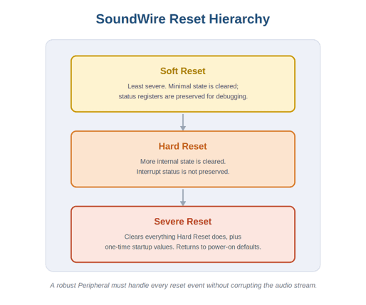
Error injection here means sequencing these resets at the worst possible moments (mid-command, mid-stream, back-to-back) and confirming the Peripheral handles every combination without corrupting the audio stream when activity returns.
Conclusion
A Peripheral that behaves correctly on a clean bus has done only part of its job. The remainder is behaviour at the edges: when synchronization drifts, when a parity bit is corrupted, when a reset arrives at an inconvenient moment (the part, the end users actually notice). Error injection turns SoundWire’s rich error model into demonstrated robustness on real silicon, and it remains one of the most effective ways to prove compliance, accelerate debug, and deliver audio products that behave predictably in the field.
Soliton’s Validation Tool helps engineering teams carry out exactly this kind of structured error injection across SoundWire, SWI3S, and a wide range of other digital interfaces so that the recovery paths the specification defines can be exercised systematically rather than left to chance.
References
For readers who would like a foundational understanding of the protocols discussed in this blog:
- MIPI SoundWire Specification Overview: https://www.mipi.org/specifications/soundwire
- MIPI SWI3S (SoundWire I3S) Overview: https://www.mipi.org/mipi-soundwire-i3s