Introducing SafeSPI, a standardized format addressing communication challenges posed by custom SPI versions in complex systems like automotive platforms. SafeSPI enhances interoperability and streamlines development processes in sensor communication. It features specific addressing modes and fixed frame lengths, providing standards for data transmission.
The Serial Protocol Interface (SPI) is a 4-wire synchronous communication interface between microcontrollers and sensors, which serves as a foundational digital protocol. Despite its flexibility, the prevalence of custom SPI versions amongst engineers has complicated integrating multiple devices into a single system. In complex systems like automotive platforms, the varied SPI formats across sensors create communication challenges, prompting the need for standardization.
This need led to the birth of SafeSPI, a standardized format addressing the challenges posed by custom SPI versions. The SafeSPI initiative aims to streamline specifications and simplify communication in diverse device environments, offering a solution to the complexities introduced by the varied SPI formats across different sensors and platforms.
How does SafeSPI differ from the SPI?

The Serial Peripheral Interface for Automotive Safety (SafeSPI) is an open standard based on the SPI industry standard.
SafeSPI is a pivotal interface in automotive applications, facilitating the seamless transmission of data across sensors and devices. By standardizing specific protocol options, the SafeSPI automotive protocol helps enhance interoperability and streamline the development process for new systems, devices, and software. Much like the conventional SPI interface, SafeSPI pin configurations follow the standard SPI protocol, carrying four pins: chip select (CS), serial clock (SCK), master out slave in (MOSI), and master in slave out (MISO). The main difference is in how SafeSPI defines the communication specifications.
These parameters and specifications can be seen on the SafeSPI website or datasheet.
Different Formats of SafeSPI
With SafeSPI becoming a standard in automotive applications as a means of sensor communication, the SafeSPI community has declared some criteria or standards that the interface needs to follow. Even though there are numerous standards to declare SafeSPI, two major formats hold a greater priority.
Let us now discuss two of the major formats of SafeSPI and their standards.
SafeSPI Slave Addressing
Unlike SPI, which can have any type of addressing, SafeSPI can only have five types of addressing modes as listed below,
- Slave addressing using CS, all slave devices carry separate CS lines like standard SPI.
- Select 2 slaves by address pins; 2 slaves can be addressed by the address bit from MOSI.
- Select 2 slaves by address pins by saving the addresses as fixed in the non-volatile memory on the slave side. MOSI is used to send addresses.
- Select 4 slaves by address pins; 4 slaves can be addressed by the address bit from MOSI.
- Select 4 slaves by address pins by saving the addresses as fixed in the non-volatile memory on the slave side. MOSI is used to send addresses.

SafeSPI Fixed Data-Frame Lengths
SafeSPI has fixed frame lengths, which creates a standard of communication between sensors and devices, enhancing interoperability. Below are some admittable standards of data transmission for the sensor to be SafeSPI compliant.
- Compared to SPI, which allows flexible data-frame lengths, SafeSPI standards specify 32-bit and 48-bit frame lengths.
- SafeSPI specifies that for the data-frame length of 32Bit, both In-frame (if) and Out-Of Frame (oof) communication is supported, while for 48-bit frame length, only out-of-frame is defined.
- For 32-bit or 48-bit in-frame mode, the data of the slave response is within the same time slot as the master’s request, while for the Out-Of-Frame, the logical response of the slave is within the next frame of the master.
- The 32-bit and 48-bit modes can be either selected by using the chip-select (CS) or the address of the target device.
- If a single target device supports 32-bit and 48-bit modes and CS is used for specifying the data length, 2 pins can be used. CS32 and CS48 are for 32-bit and 48-bit data transfer, respectively. This increases the number of CS lines. If addresses are used to switch between data-frame lengths, the MOSI (master out slave in) pins follow a specific command format to switch between the modes.
Consider the following example illustrating the 32-bit out-of-frame transaction within the SafeSPI protocol framework:
Master transmission in 32–bit out–of–frame transaction

Slave response in 32–bit out-of-frame transaction

SafeSPI Fixed Data-Frame Lengths meticulously define the communication intricacies between the Controller and Target devices. The target (MOSI 31-22) and source address (MISO 30-21) exhibit variability based on the chosen addressing type. The first 2 bits are mandatory, and depending on the addressing format followed, these 2 bits vary. The rest of the 8 bits are optional.
The Frame Types are defined by bit 19 for MOSI and bit 31 for MISO and are used to discern the type of function. The actual data is transmitted through the bits 18 to 3 in MOSI and 19 to 4 in MISO. Additionally, S1 at 20 and S0 at 3 serve as markers, delineating the type of information the sensor carries: ’00’ for valid sensor data, ’01’ for a sensor in an error state, ’11’ signifying initialization state with ensuing sensor data, and ’10’ left for custom use. Capping off the sequence, the CRC bits at 2, 1, and 0 seamlessly perform error calculations.
Boost your Compliance Validation of SafeSPI with Soliton
Navigating the compliance metrics of SafeSPI in automotive devices demands time, energy, and capital —especially when steering away from protocol exercisers or ATE solutions towards DIY alternatives.
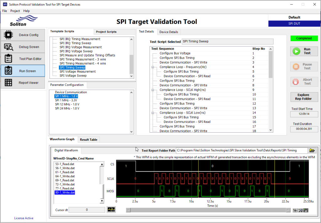
Enter Soliton’s turnkey solutions for SPI validation. With our SPI Target Validation Tool, SPI and SafeSPI compliance validation becomes a streamlined and straightforward process, resulting in effort reduction, enhanced ROIs, and an accelerated journey to market.

To know more details, functional coverage, parametric coverage, and features of PVS’s SPI Protocol Validation, click here.